
media coverage
A reverse osmosis system is far more than a simple assembly of membrane vessels and pumps - it is a sophisticated separation technology grounded in thermodynamics and materials science. By understanding the fundamental principles that govern its operation, we unlock the key to achieving high-efficiency performance and long-term operational stability.
1. Reverse Osmosis Technology
When people talk about reverse osmosis, many assume it simply "pushes water through a membrane with pressure". The description sounds intuitive, but it oversimplifies - and even distorts - the real science. True reverse osmosis is a precisely engineered process, an industrial-scale "defiance" of natural laws.
1) Osmosis: Nature’s Rule
Picture a membrane that allows only water molecules to pass through, separating pure water from saline water. Naturally, water moves from the pure side to the saline side in an attempt to dilute it and reach concentration balance.
This spontaneous behavior is known as osmosis, driven by a force called osmotic pressure.
2) Reverse Osmosis: Engineering the "Against-Nature" Path
To obtain clean water from saline water, we must force the system to run counter to nature. By applying pressure greater than the osmotic pressure on the saline side, water molecules are driven backward - toward the pure-water side - while salts, colloids, and organic contaminants are rejected by the membrane.
This engineered reversal is what we call reverse osmosis.
Key Formula: How Is Osmotic Pressure Calculated
Osmotic pressure can be estimated using the Van’t Hoff equation: π = i × C × R × T
π: Osmotic pressure
i: Van’t Hoff factor (≈2 for NaCl)
C: Molar concentration
R: Gas constant
T: Absolute temperature
Temperature effect: Higher temperature, higher osmotic pressure, higher operating pressure. This explains seasonal pressure adjustments in RO systems.
Dynamic concentration rise: Solute concentration increases along the membrane flow path, creating different osmotic pressures and making the concentrate end the most prone to scaling.
3) Separation Mechanism: How Does the Membrane "Choose" What Passes Through?

For RO, the commonly used "sieving" analogy is not fully adequate. Modern polyamide composite RO membranes follow the solution-diffusion model:
Water molecules first dissolve into the polymer network, then diffuse through the membrane under pressure and concentration gradients, finally desorb on the permeate side. Larger hydrated ions and molecules cannot dissolve or diffuse efficiently, so they are effectively rejected.
The process resembles a molecular-level race, not a simplistic sieve.
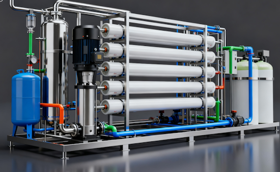
2. RO Membrane Elements
The RO membrane element is the heart of a reverse osmosis system, and its technological sophistication defines the system’s ultimate performance ceiling.
1) A Materials Breakthrough: Polyamide Composite Membranes
Modern RO membranes are no longer homogeneous cellulose acetate types, but thin-film composite (TFC) polyamide membranes manufactured by interfacial polymerization.
It is composed of three engineered layers:
Polyester non woven support layer - provides mechanical strength
Porous poly sulfone layer - offers structural rigidity and smooth morphology
Polyamide active layer (~200 nm) - the ultra-thin dense layer where desalination occurs
This architecture delivers high permeability, excellent chemical stability (wide pH tolerance), and >99% salt rejection. However, it has an Achilles heel - extreme sensitivity to oxidants, particularly free chlorine, which can irreversibly damage the membrane.
2) Key Performance Metrics: How to Read a Membrane
Salt Rejection = (1 - Permeate TDS / Feed TDS) × 100%. A higher rejection reflects more advanced membrane manufacturing and tighter selectivity.
Permeate Flux: The volume of product water generated per membrane area per unit time. Excessively high flux accelerates fouling, while overly low flux increases capital cost - making optimization essential.
Recovery Rate = Permeate Flow / Feed Flow × 100%. Higher recovery saves water but also concentrates solutes, increasing fouling and scaling tendencies.
Salt rejection, flux, and recovery are tightly interconnected: At higher recovery - concentrate salinity rises - osmotic pressure increases. Higher osmotic pressure reduces the net driving pressure, resulting in lower flux. Meanwhile, a greater concentration gradient can slightly reduce salt rejection.
In short: Optimizing any single parameter requires understanding the system holistically.
3. The Engineering Logic of an RO System
A well-engineered RO system is built on design logic that prevents problems before they occur.
1) Pretreatment: The RO System’s "Immune System"
Pretreatment serves one purpose: to ensure the feed water meets the membrane’s protection requirements, shaped entirely by raw-water quality and membrane sensitivity. Multimedia filtration removes suspended solids, activated carbon eliminates residual chlorine, softening reduces hardness, and antiscalants prevent scaling. Each step acts as a defensive barrier, safeguarding the membrane - the heart of the system.
2) Pressure Vessel Arrangement and Staging: The "Art" of RO Design
Why aren’t RO pressure vessels simply arranged in parallel?
Because the goal is to optimize feed utilization and maximize recovery under limited operating pressure.
Stage 1: Parallel elements producing the bulk of permeate
Stage 2: Treats Stage 1 concentrate to recover additional water
Second Pass: Reprocesses permeate for higher purity, common in ultra pure water systems
The classic "2:1" design (e.g., 6 vessels in Stage 1 and 3 in Stage 2) balances flux across stages, preventing Stage-2 fouling caused by insufficient flow.
3) The System’s "Neural Network": Monitoring and Diagnostics
Every key instrument in the RO system acts as a diagnostic sensor:
Feed/Concentrate Pressure: Used to determine ΔP for fouling diagnosis.
Permeate Flow: A core performance metric; normalized trends reveal fouling early.
Feed/Permeate Conductivity: A direct indicator of salt rejection performance.
SDI: Online indicator of pretreatment effectiveness - the RO system’s first sentinel.
Only by understanding the dynamic balance between pressure, concentration, and flux can engineers diagnose issues confidently and take effective action in real-world operation.
In upcoming sections, we will explore pretreatment optimization, chemical cleaning strategies, and practical troubleshooting techniques.


